Chapter 3: Application Scenarios
3.1 Scenario Overview and Comparison Matrix
Critical medical equipment PDUs serve diverse clinical environments, each with unique power requirements, reliability expectations, and operational constraints. Understanding these scenario-specific requirements is essential for selecting appropriately configured solutions that balance performance, reliability, and cost. This chapter examines five primary application scenarios: operating rooms, intensive care units, emergency departments, cardiac catheterization laboratories, and imaging suites. Each scenario is analyzed across multiple dimensions including typical load characteristics, redundancy requirements, monitoring needs, environmental conditions, and regulatory considerations.
The following comparison matrix provides a high-level overview of key characteristics across these scenarios, enabling procurement teams to quickly identify which scenario best matches their specific application and understand the relative requirements across different clinical environments.
| Scenario | Typical Load per Room | Redundancy Level | Acceptable Downtime | Grounding System | Monitoring Priority | Environmental Factors |
|---|---|---|---|---|---|---|
| Operating Room | 8-15 kW | Dual-path with ATS | Zero (life-critical) | IT (isolated) | Critical - real-time | Cleanroom, high humidity |
| Intensive Care Unit | 3-6 kW per bed | N+1 or dual-path | Zero (life-critical) | TN or IT | Critical - real-time | 24/7 operation, moderate cleanliness |
| Emergency Department | 5-10 kW per bay | N+1 minimum | Minimal (seconds) | TN with GFCI | High - rapid response | Variable load, high utilization |
| Cardiac Cath Lab | 15-25 kW | Dual-path with ATS | Zero (life-critical) | IT (isolated) | Critical - real-time | Imaging equipment, high power |
| Imaging Suite (CT/MRI) | 25-50 kW | Single-path acceptable | Minutes (schedulable) | TN with dedicated ground | Moderate - scheduled checks | High power, EMI sensitive |
3.2 Scenario 1: Operating Rooms
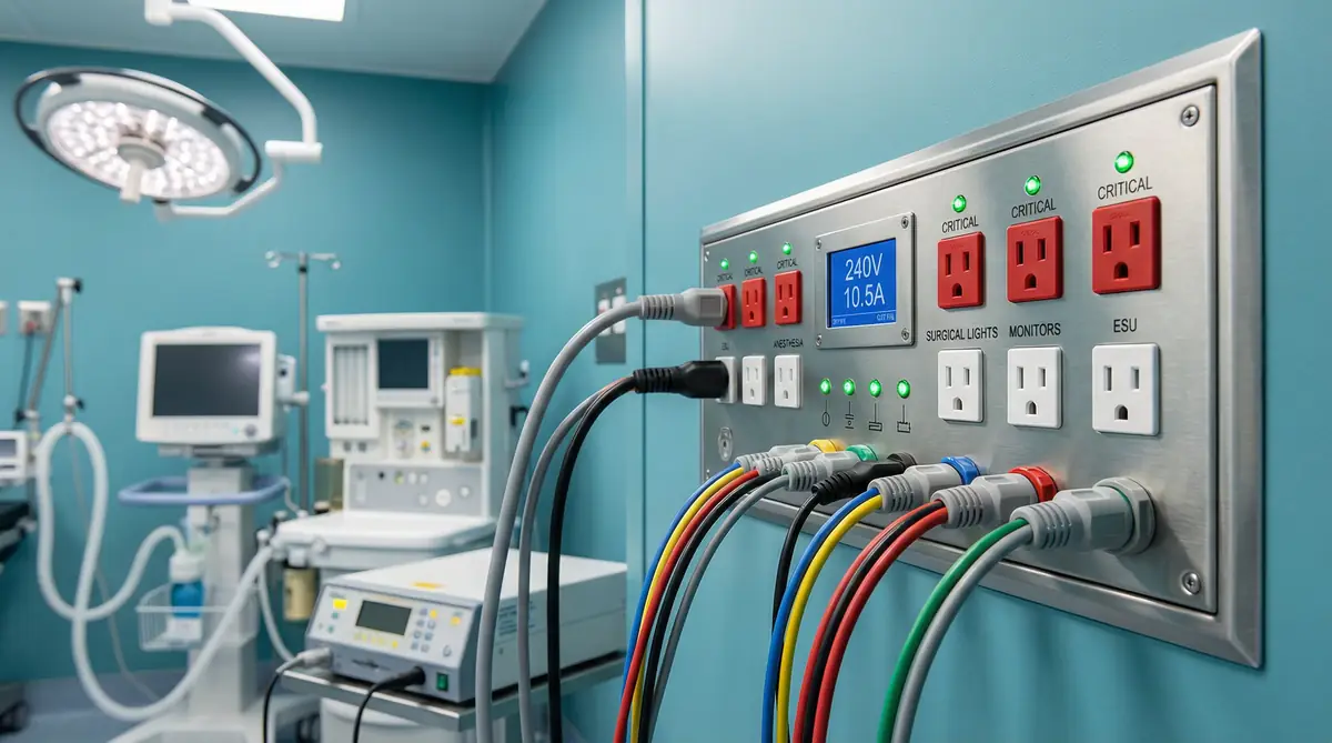
Figure 3.1: Modern hospital operating room with advanced surgical equipment and medical-grade power distribution
Load Characteristics and Equipment Profile
Operating rooms represent one of the most demanding applications for medical PDUs, combining high power requirements with absolute reliability expectations and stringent electrical safety requirements. A typical operating room contains anesthesia delivery systems (1,500-2,500W), surgical lighting systems (500-1,500W), electrosurgical units (400-800W), patient monitoring systems (200-500W), imaging equipment such as C-arms or portable X-ray (2,000-5,000W), warming devices for patients and fluids (500-1,000W), and powered surgical instruments (300-800W). The total connected load typically ranges from 8,000W to 15,000W depending on the surgical specialty and equipment complement.
Load profiles in operating rooms are highly dynamic, with significant variations between different phases of surgical procedures. During patient preparation and positioning, power demand is relatively low, primarily consisting of lighting, monitoring, and anesthesia equipment. During active surgical phases, demand increases substantially as electrosurgical units, powered instruments, and imaging equipment are activated. Peak demand occurs when multiple high-power devices operate simultaneously, such as during complex procedures requiring continuous imaging guidance. The PDU must accommodate these peak loads without voltage sags or breaker trips that could disrupt critical procedures.
Redundancy and Reliability Requirements
Operating rooms tolerate absolutely no power interruption during active surgical procedures, as loss of power to anesthesia delivery systems, patient monitoring, or surgical lighting could result in patient death or serious injury. This requirement mandates dual-input PDUs with automatic transfer switching capability, ensuring seamless transition between primary and backup power sources during upstream failures or maintenance. The transfer time must be sufficiently fast (typically under 100 milliseconds for mechanical switches, under 10 milliseconds for static switches) to prevent interruption of sensitive equipment. Bypass paths must enable PDU maintenance without interrupting power to connected loads, typically requiring parallel PDUs or temporary distribution equipment during service.
Grounding and Electrical Safety
Operating rooms universally employ isolated power (IT) systems where the power distribution system is not connected to ground, significantly reducing the risk of electrical shock to patients who may be electrically susceptible due to invasive monitoring or surgical procedures. The PDU must integrate with the isolation transformer and include an insulation monitoring device (IMD) that continuously measures the impedance between the power system and ground. When insulation resistance falls below safe thresholds (typically 50-100 kΩ depending on system size), the IMD triggers visual and audible alarms without interrupting power, allowing the surgical team to complete the procedure while facilities staff investigate the fault. The alarm system must provide clear indication of which line (L1 or L2) has reduced insulation, facilitating rapid troubleshooting.
Environmental and Installation Considerations
Operating rooms are classified as cleanrooms with strict requirements for surface materials, air quality, and infection control protocols. PDU enclosures must feature smooth, non-porous surfaces that can withstand repeated cleaning with hospital-grade disinfectants including bleach, quaternary ammonium compounds, and hydrogen peroxide vapor. Stainless steel construction is preferred for its corrosion resistance and ease of cleaning. All seams must be sealed to prevent pathogen harboring, and external surfaces should minimize crevices and recesses. The enclosure must achieve appropriate IP (Ingress Protection) rating to prevent moisture ingress during cleaning procedures, typically IP54 or higher. Installation location must consider surgical workflow, ensuring that PDU access for maintenance does not interfere with sterile fields or equipment positioning during procedures.
Monitoring and Alarm Requirements
Operating room PDUs require comprehensive real-time monitoring with immediate alarm notification for any abnormal condition. Critical monitored parameters include input voltage and frequency on both primary and secondary power sources, total load current and power with trending to detect gradual increases, individual branch circuit loading to identify overload conditions before breaker trips occur, insulation resistance with continuous IMD monitoring and immediate alarming, and internal temperature to detect cooling problems or excessive ambient temperature. Alarms must provide local visual and audible indication within the operating room, but volume and intensity must be adjustable to avoid disrupting surgical concentration. Remote alarms must notify facilities management and biomedical engineering staff through the hospital's building management system, enabling rapid response without relying on surgical staff to report problems.
3.3 Scenario 2: Intensive Care Units
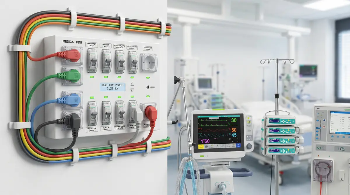
Figure 3.2: ICU patient room with ventilator, patient monitors, and multiple IV infusion pumps requiring continuous power
Load Characteristics and Equipment Profile
Intensive care units provide continuous monitoring and life support for critically ill patients, with each bed space containing multiple pieces of equipment that cannot tolerate power interruption. A typical ICU bed includes mechanical ventilators (300-800W), infusion pumps for medications and nutrition (50-150W per pump, with 4-8 pumps per bed), patient monitors tracking vital signs (150-300W), warming blankets and fluid warmers (200-500W), and specialized equipment depending on patient condition such as dialysis machines (500-1,000W), intra-aortic balloon pumps (200-400W), or extracorporeal membrane oxygenation (ECMO) systems (500-1,500W). The total load per bed typically ranges from 3,000W to 6,000W, with some beds exceeding 8,000W when multiple specialized support systems are required.
Unlike operating rooms where equipment is activated for specific procedures, ICU equipment operates continuously for extended periods, often days or weeks. Load profiles are relatively stable during steady-state patient care, but can change rapidly when patient condition deteriorates and additional interventions are required. The PDU must accommodate sudden addition of high-power equipment such as portable X-ray machines, ultrasound systems, or additional warming devices without causing voltage sags or overload conditions that could affect other patients in the unit.
Redundancy and Reliability Requirements
ICU patients depend on continuous power for life support, making redundancy essential. The appropriate redundancy level depends on unit size and configuration. Smaller ICUs (4-8 beds) may use N+1 redundancy where a single PDU failure can be tolerated because redundant capacity exists in parallel PDUs. Larger ICUs typically employ dual-path redundancy where each bed space receives power from two independent PDUs connected to separate upstream sources, with critical equipment distributed across both circuits. Automatic transfer switching is highly desirable but not always mandatory if clinical staff can manually switch equipment to backup circuits during failures. The key requirement is that no single PDU failure can result in complete loss of power to any bed space.
Capacity Planning and Scalability
ICU power requirements evolve as medical technology advances and treatment protocols change. Equipment that was rare a decade ago, such as ECMO systems, is now routine in many ICUs. PDU capacity must accommodate current loads plus reasonable growth margin, typically 30-50% above current peak demand. Branch circuit configuration must provide flexibility to connect equipment in various configurations as patient needs change. A common approach is to provide multiple 20A circuits at each bed space rather than fewer high-capacity circuits, enabling better load distribution and reducing the impact of individual circuit failures. Spare capacity should be distributed across multiple PDUs to maintain redundancy as load increases.
Monitoring and Alarm Requirements
ICU PDUs require continuous monitoring with rapid alarm notification, but alarm management must consider the high-alarm environment of ICUs where numerous devices generate frequent alarms. PDU alarms must be prioritized appropriately, with life-threatening conditions (complete power loss, imminent overload) generating high-priority alarms that demand immediate attention, while less critical conditions (moderate load increase, minor voltage deviation) generate lower-priority notifications that can be addressed during routine rounds. Integration with the hospital's alarm management system enables coordinated alarm escalation and ensures that critical power alarms are not lost among the numerous clinical alarms generated by patient monitoring equipment. Historical data logging is particularly valuable in ICUs for identifying trends in power consumption that may indicate equipment problems or changing patient acuity.
3.4 Scenario 3: Emergency Departments
Figure 3.3: Emergency department trauma bay with crash cart, portable imaging equipment, and multiple monitoring systems
Load Characteristics and Operational Patterns
Emergency departments present unique challenges due to highly variable and unpredictable load patterns. Unlike ICUs where patients remain for extended periods with relatively stable equipment needs, emergency departments experience rapid patient turnover with equipment being connected and disconnected frequently. Each treatment bay contains basic monitoring equipment (150-300W), but additional equipment is brought in as needed including portable X-ray machines (2,000-4,000W), ultrasound systems (300-600W), warming devices (500-1,000W), and emergency resuscitation equipment including defibrillators and mechanical CPR devices (200-500W). The total load per bay can range from minimal (single patient monitor) to 8,000W or more during major resuscitations.
The challenge for PDU sizing is accommodating peak demand scenarios where multiple bays simultaneously require high-power equipment during mass casualty incidents or periods of high patient volume. Diversity factors are less favorable than in ICUs because emergency departments regularly experience scenarios where most or all bays are simultaneously occupied with high-acuity patients. PDU capacity must be sized for these peak scenarios even though average utilization may be much lower, resulting in systems that operate at relatively low load factors during normal operations.
Reliability and Response Time Requirements
Emergency departments require high reliability but can tolerate brief interruptions more readily than operating rooms or ICUs, as most emergency procedures can be briefly paused if necessary. However, response time to power problems must be extremely rapid because patient conditions can deteriorate quickly. Redundancy requirements are typically N+1 rather than full dual-path, with the understanding that brief manual intervention to redistribute loads may be acceptable during PDU failures. The critical requirement is rapid notification of problems and clear indication of which circuits are affected, enabling clinical and facilities staff to quickly implement workarounds. Battery backup for critical equipment (monitors, ventilators) provides a buffer during power transitions, reducing the urgency of power restoration compared to environments without local battery backup.
Flexibility and Reconfiguration
Emergency department layouts and workflows evolve frequently as patient volumes change and treatment protocols are updated. PDU configurations must provide maximum flexibility to accommodate these changes without requiring electrical infrastructure modifications. This typically means providing more branch circuits with lower individual capacity rather than fewer high-capacity circuits, enabling equipment to be connected in various configurations. Receptacle types should accommodate a wide variety of equipment, with a mix of standard hospital-grade receptacles and specialized connectors for high-power devices. The PDU should be located to minimize cable runs to treatment bays while maintaining accessibility for maintenance without disrupting clinical operations.
3.5 Scenario 4: Cardiac Catheterization Laboratories
Figure 3.4: Cardiac catheterization laboratory with C-arm fluoroscopy system and hemodynamic monitoring equipment
Load Characteristics and Equipment Profile
Cardiac catheterization laboratories combine the high power demands of imaging equipment with the life-critical reliability requirements of interventional procedures. A typical cath lab contains fluoroscopy/angiography imaging systems (8,000-15,000W), hemodynamic monitoring systems (500-1,000W), intra-aortic balloon pumps and other circulatory support devices (300-800W), physiologic recording systems (200-400W), and contrast injection systems (300-600W). Total connected load typically ranges from 15,000W to 25,000W, with peak demand occurring during active imaging sequences when the X-ray generator is energized. These peak demands are brief (typically seconds) but occur frequently throughout procedures, requiring PDU capacity to accommodate repetitive peak loads without voltage sags that could affect image quality or disrupt other equipment.
Power Quality and Imaging Equipment Requirements
Imaging equipment in cath labs is highly sensitive to power quality issues. Voltage sags during X-ray exposures can cause image artifacts or system faults. Harmonic distortion from imaging equipment power supplies can affect other connected equipment if not properly managed. The PDU must provide stable voltage regulation under varying load conditions, with voltage deviation typically limited to ±3% during load transients. Input filtering or isolation transformers may be required to prevent imaging equipment harmonics from propagating to other loads. Branch circuit protection must be carefully coordinated to avoid nuisance trips during the high inrush currents associated with imaging equipment startup, while still providing adequate protection against sustained overload or fault conditions.
Redundancy for Life-Critical Procedures
Many cardiac catheterization procedures are life-critical interventions where power interruption could result in patient death. Patients undergoing complex interventions such as percutaneous valve replacements or high-risk angioplasty may be hemodynamically unstable and completely dependent on circulatory support devices and continuous monitoring. These scenarios require dual-path power distribution with automatic transfer switching, similar to operating rooms. However, unlike operating rooms where all equipment is life-critical, cath labs can implement tiered power distribution where imaging equipment receives single-path power (acceptable brief interruption for image quality but not life-threatening) while patient monitoring and support equipment receives dual-path power (zero interruption tolerance). This approach optimizes cost while ensuring patient safety.
3.6 Scenario 5: Imaging Suites (CT/MRI)
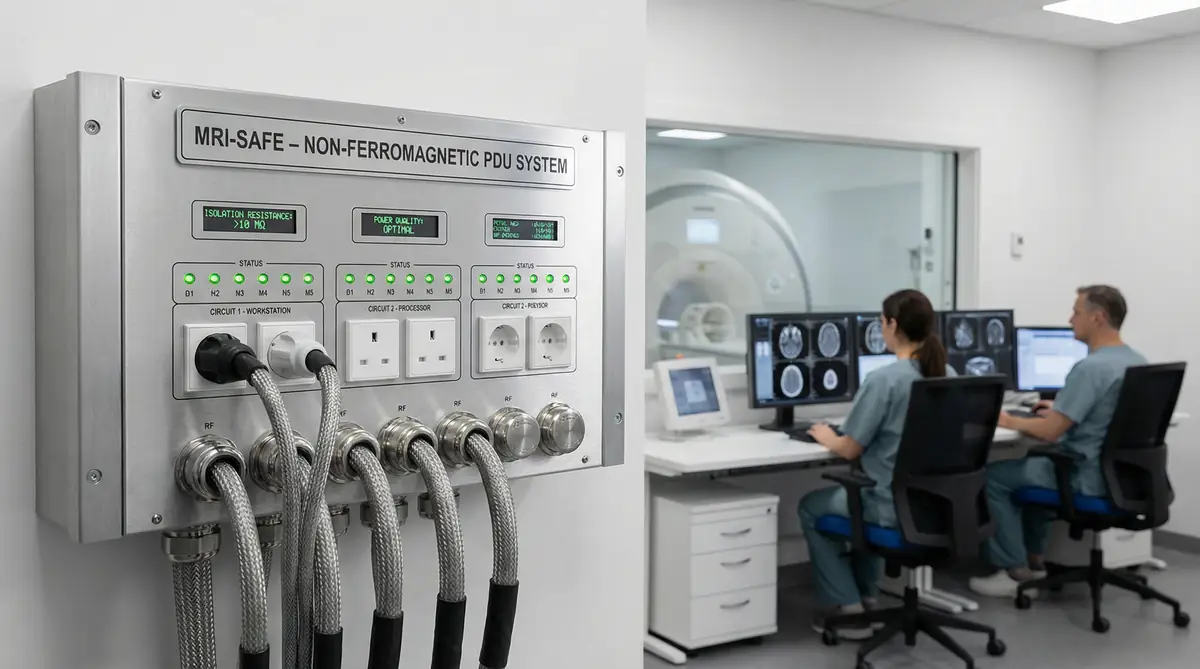
Figure 3.5: Medical imaging suite showing CT scanner and control room with multiple workstations and equipment racks
Load Characteristics and Power Requirements
Advanced imaging systems including computed tomography (CT) and magnetic resonance imaging (MRI) scanners represent the highest power loads in most hospitals, with individual systems consuming 25,000W to 50,000W or more. These loads often exceed the capacity of typical medical PDUs, requiring dedicated circuits from distribution panels rather than connection through PDUs. However, imaging suites contain numerous auxiliary systems that are appropriate for PDU distribution including patient monitoring equipment (200-400W), contrast injection systems (500-1,000W), anesthesia equipment for sedated patients (1,500-2,500W), and HVAC systems for equipment cooling (2,000-5,000W). The PDU must coordinate with the main scanner power distribution, ensuring that auxiliary equipment receives appropriate protection and monitoring without interfering with scanner operation.
Electromagnetic Compatibility Considerations
MRI suites present unique challenges due to the intense magnetic fields generated by the scanners. All electrical equipment within the MRI room must be non-ferromagnetic to prevent attraction to the magnet, which could cause equipment damage or serious injury. PDUs serving MRI rooms are typically located outside the magnetic field zone, with non-ferromagnetic cable assemblies penetrating the shielded room. Proper grounding and shielding are essential to prevent radiofrequency interference from external equipment affecting image quality. The PDU must integrate with the MRI room's RF shielding, ensuring that power cables do not compromise the shielded enclosure. CT suites have less stringent requirements but still require attention to electromagnetic compatibility to prevent interference with sensitive imaging electronics.
Reliability and Scheduling Considerations
Unlike operating rooms and ICUs where procedures cannot be interrupted, imaging procedures can typically be rescheduled if equipment failures occur. This allows more flexibility in redundancy requirements, with single-path power distribution often acceptable if adequate preventive maintenance and rapid repair capabilities are in place. The key consideration is minimizing unscheduled downtime that disrupts patient schedules and reduces equipment utilization. Comprehensive monitoring with predictive maintenance capabilities helps identify developing problems before they cause failures, enabling repairs to be scheduled during planned downtime periods. When redundancy is required, it is typically implemented at the facility level (backup generator, UPS) rather than at the PDU level, as the high power demands make PDU-level redundancy cost-prohibitive.
3.7 Scenario 6: Post-Anesthesia Care Units (PACU) / Recovery Rooms
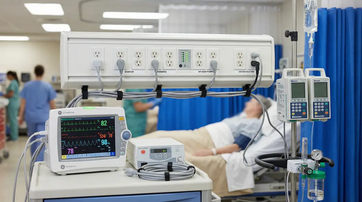
Figure 3.6: PACU recovery bay with patient monitoring, warming systems, and multiple infusion pumps
Load Characteristics and Equipment Profile
Post-anesthesia care units provide immediate post-operative monitoring and recovery support for patients emerging from anesthesia. The power requirements in PACU environments share characteristics with both operating rooms and ICUs, combining moderate equipment density with critical patient monitoring needs. A typical PACU bay contains patient monitors tracking vital signs including ECG, blood pressure, oxygen saturation, and respiratory rate (150-300W), oxygen delivery systems including nasal cannulas, face masks, or mechanical ventilators for patients requiring continued respiratory support (300-800W for ventilators), warming devices to prevent hypothermia as patients recover from anesthesia (500-1,000W), infusion pumps delivering pain medications, fluids, and other therapeutics (50-150W per pump, with 2-4 pumps per bay), and suction equipment for airway management (200-400W). The total load per bay typically ranges from 2,000W to 4,000W, with higher demands when patients require mechanical ventilation or intensive warming.
PACU environments experience highly variable occupancy and acuity patterns. During peak surgical schedules, all bays may be simultaneously occupied with patients requiring full monitoring and support. During off-peak periods or overnight, occupancy may be minimal. Equipment utilization also varies significantly based on patient condition, with some patients requiring only basic monitoring while others need intensive support approaching ICU-level care. The PDU must accommodate these variations in load, providing sufficient capacity for peak scenarios while operating efficiently during lower-demand periods. Unlike ICUs where patients remain for extended periods, PACU stays are typically measured in hours, resulting in frequent equipment connection and disconnection cycles that stress receptacles and increase wear on electrical components.
Redundancy and Reliability Requirements
PACU patients are typically less critically ill than ICU patients, as they are recovering from planned surgical procedures rather than experiencing acute medical crises. However, some PACU patients remain physiologically unstable, particularly those recovering from major surgery, patients with significant comorbidities, or patients experiencing post-operative complications. Power reliability requirements must reflect this mixed acuity, providing high reliability without the absolute zero-tolerance approach required in operating rooms. N+1 redundancy is typically appropriate, ensuring that a single PDU failure does not result in complete loss of power to any bay but accepting that brief manual intervention may be required to redistribute loads during failures.
The key consideration is rapid identification and response to power problems. PACU clinical staff must be immediately notified of any power issues so they can implement appropriate interventions, which may include manually switching equipment to backup circuits, transferring patients to alternative bays with functioning power, or in extreme cases transferring patients back to ICU or operating room environments with more robust power systems. Clear visual indication of power status, both at individual bays and at the unit level, enables staff to quickly assess the situation and implement appropriate responses. Battery backup in critical equipment provides a buffer during power transitions, reducing the urgency of power restoration compared to environments without local battery backup.
Capacity Planning and Flexibility
PACU capacity requirements are driven by surgical volume and case mix, which can change significantly over time as surgical programs expand or contract and as surgical techniques evolve. Minimally invasive surgical approaches may reduce PACU length of stay and equipment requirements, while complex procedures may increase both. PDU capacity must accommodate current peak demand plus reasonable growth margin, typically 30-40% above current maximum utilization. This growth margin is particularly important in PACU environments because surgical volume can increase rapidly when new surgeons join the staff or when new surgical programs are established.
Flexibility in equipment configuration is essential because PACU bays must accommodate a wide range of patient conditions and equipment needs. Some patients require only basic monitoring, while others need full ventilatory support, multiple infusions, and intensive warming. The PDU should provide multiple branch circuits at each bay, enabling equipment to be connected in various configurations without overloading individual circuits. A common approach is to provide at least four 20A circuits per bay, distributed across different phases to balance load and maintain capacity if one phase experiences problems. Additional circuits should be available for shared equipment such as portable X-ray machines, ultrasound systems, or specialized monitoring equipment that moves between bays as needed.
3.8 Scenario 7: Neonatal Intensive Care Units (NICU)
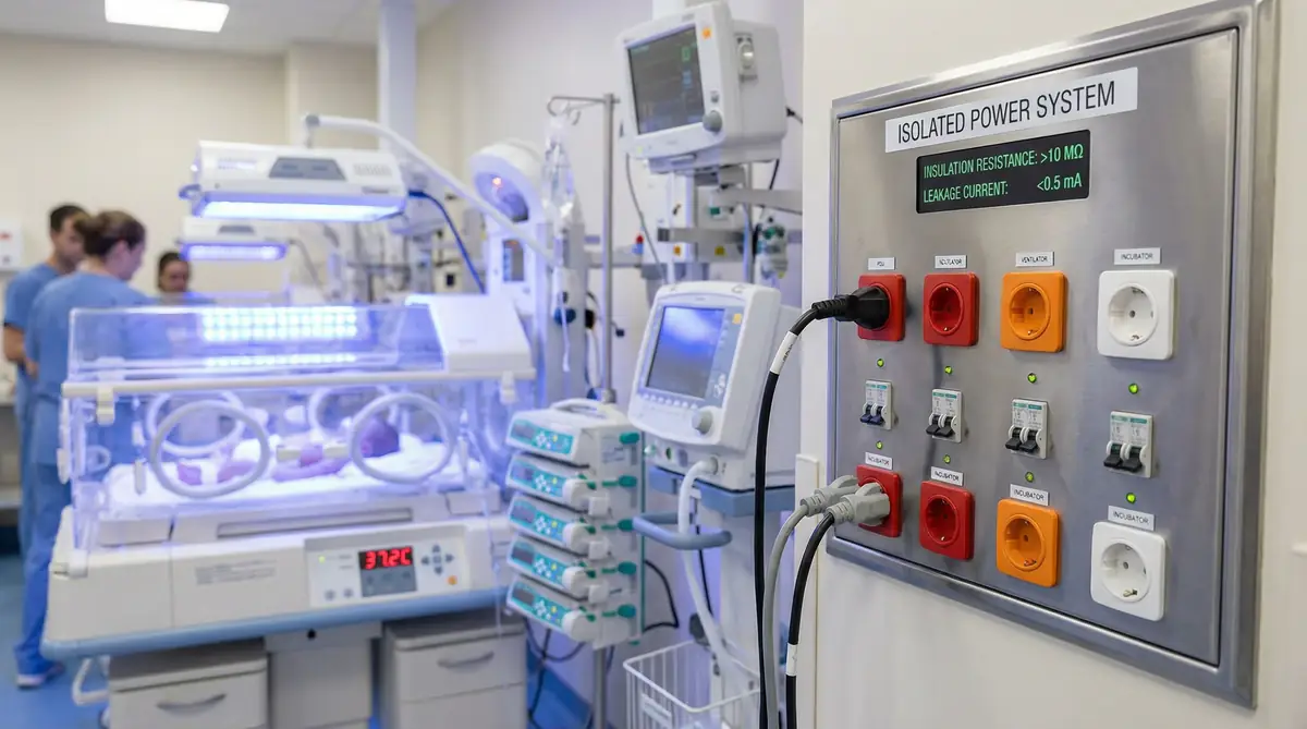
Figure 3.7: NICU with infant incubator, neonatal ventilator, precision infusion pumps, and phototherapy lights
Load Characteristics and Equipment Profile
Neonatal intensive care units provide specialized care for premature infants and critically ill newborns, with unique power requirements driven by the small size and physiological fragility of patients. A typical NICU bed space contains specialized equipment including infant ventilators or CPAP systems delivering respiratory support with precise pressure and oxygen control (200-400W), radiant warmers or incubators maintaining precise temperature control essential for premature infant survival (400-800W), phototherapy lights treating neonatal jaundice (150-300W), infusion pumps delivering medications and nutrition in very small volumes requiring high precision (50-100W per pump, with 4-8 pumps per bed), patient monitors tracking vital signs with specialized neonatal sensors (150-250W), and specialized equipment such as high-frequency ventilators, nitric oxide delivery systems, or cooling systems for therapeutic hypothermia (300-1,000W depending on therapy). The total load per bed typically ranges from 2,000W to 5,000W, with higher demands for the most critically ill infants requiring multiple intensive therapies.
NICU equipment operates continuously for extended periods, often weeks or months for extremely premature infants. Unlike adult ICUs where equipment may be adjusted frequently, NICU equipment settings are often maintained relatively stable once optimal parameters are established, as frequent changes can stress fragile infants. This results in relatively stable power profiles during steady-state care, with changes occurring primarily when new therapies are initiated or when patients are transitioned between different levels of support. However, emergency situations such as sudden deterioration or resuscitation events can result in rapid addition of high-power equipment, requiring the PDU to accommodate sudden load increases without voltage sags that could affect other infants in the unit.
Specialized Safety and Grounding Requirements
Neonatal patients are particularly vulnerable to electrical hazards due to their small size, immature physiology, and the invasive monitoring and therapeutic interventions they receive. Extremely premature infants may weigh less than 500 grams, making them exquisitely sensitive to even tiny electrical currents that would be imperceptible to adults. Many NICU patients have invasive lines including umbilical catheters that provide direct electrical pathways to the heart, creating conditions where microshock (currents as low as 10-100 microamperes applied directly to the heart) can cause fatal arrhythmias. These considerations mandate the most stringent electrical safety requirements in the hospital.
NICU environments typically employ isolated power (IT) systems similar to operating rooms, where the power distribution is not connected to ground, significantly reducing leakage current and shock risk. The PDU must integrate with the isolation transformer and include continuous insulation monitoring with immediate alarming if insulation resistance falls below safe thresholds. However, unlike operating rooms where alarms can be relatively loud to ensure surgical team awareness, NICU alarms must be carefully managed to avoid creating excessive noise that can harm developing infant neurological systems. Visual alarm indication must be prominent, but audible alarms should be modulated to provide clear notification without creating harmful noise levels.
Redundancy and Reliability Requirements
NICU patients depend on continuous power for life support, making redundancy essential. The appropriate redundancy level depends on unit size and patient acuity. Level III and Level IV NICUs (highest acuity, caring for the most premature and critically ill infants) require dual-path power distribution with automatic transfer switching, ensuring that no single failure can interrupt power to critical equipment. Level II NICUs (intermediate care) may employ N+1 redundancy where a single PDU failure can be tolerated because redundant capacity exists in parallel PDUs, with the understanding that brief manual intervention to redistribute loads may be acceptable.
The challenge in NICU redundancy design is balancing reliability with practical considerations including cost, space constraints, and maintenance accessibility. Dual-path systems require more complex infrastructure including duplicate PDUs, transfer switches, and distribution circuits, consuming valuable space in often-cramped NICU environments. However, the consequences of power failure to vulnerable infants justify this investment in high-acuity units. A tiered approach may be appropriate, providing dual-path power to the most critical beds (those caring for extremely premature infants or infants on high-frequency ventilation or other advanced therapies) while providing N+1 redundancy to intermediate-acuity beds.
3.9 Scenario 8: Hybrid Operating Rooms
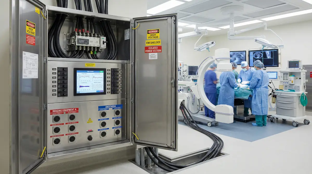
Figure 3.8: Hybrid operating room with ceiling-mounted C-arm fluoroscopy, advanced imaging displays, and high-capacity power distribution
Load Characteristics and Equipment Profile
Hybrid operating rooms combine traditional surgical capabilities with advanced imaging systems, enabling complex procedures such as endovascular interventions, cardiac surgery with intraoperative imaging, and neurosurgery with real-time imaging guidance. These environments represent the highest power demands in most hospitals, combining the equipment loads of conventional operating rooms with the addition of fixed imaging systems including C-arm fluoroscopy, CT scanners, or MRI systems. A typical hybrid OR contains all the equipment of a conventional OR including anesthesia systems (1,500-2,500W), surgical lighting (500-1,500W), electrosurgical units (400-800W), patient monitoring (200-500W), and powered surgical instruments (300-800W), plus imaging equipment including C-arm or CT systems (8,000-20,000W), image processing workstations (500-1,500W), and specialized displays for image visualization (300-800W). Total connected load typically ranges from 20,000W to 40,000W or more, with peak demand occurring when imaging systems are energized during active procedures.
The power profile in hybrid ORs is highly dynamic, with dramatic variations between different phases of procedures. During surgical preparation and initial incision, power demand is similar to conventional ORs, primarily consisting of lighting, monitoring, and basic surgical equipment. When imaging is activated for guidance or verification, power demand increases dramatically as X-ray generators or CT scanners are energized. These peak demands are typically brief (seconds for fluoroscopy, minutes for CT scans) but occur repeatedly throughout procedures, requiring PDU capacity to accommodate frequent high-magnitude load transients without voltage sags that could affect image quality or disrupt other equipment. Inrush currents when imaging equipment is energized can be particularly challenging, potentially reaching 5-10 times steady-state current for brief periods, requiring PDU components including circuit breakers and conductors to be rated for these transient conditions.
Power Quality and Imaging System Requirements
Imaging systems in hybrid ORs require high-quality, stable power to produce diagnostic-quality images. Voltage sags, transients, or harmonic distortion can degrade image quality, potentially compromising procedure outcomes. The PDU must provide clean, stable power to imaging equipment, often requiring isolation transformers, harmonic filters, or dedicated circuits separate from other OR equipment. Power factor correction may be necessary to minimize reactive power and reduce voltage drop in distribution circuits. Coordination with imaging equipment manufacturers is essential to understand specific power quality requirements and ensure that the PDU configuration meets these requirements.
Grounding systems for hybrid ORs must balance the isolated power requirements for patient safety with the grounding requirements of imaging equipment. Some imaging systems require connection to ground for proper operation and electromagnetic compatibility, creating potential conflicts with isolated power systems. Resolution typically involves using isolation transformers to provide isolated power to patient care equipment while providing grounded power to imaging systems through separate circuits. The PDU must clearly segregate these different power systems, preventing inadvertent cross-connection that could compromise either patient safety or equipment operation.
Redundancy and Reliability Requirements
Hybrid OR procedures are typically complex, high-risk interventions where power interruption could result in patient death or serious injury. Many procedures cannot be safely interrupted once begun, as patients may have open surgical sites, be dependent on cardiopulmonary bypass, or have partially deployed implants that must be completed for patient safety. These considerations mandate dual-path power distribution with automatic transfer switching for all critical equipment, ensuring seamless transition between primary and backup power sources during upstream failures or maintenance. Transfer time must be sufficiently fast to prevent interruption of imaging equipment, which may require static transfer switches (10 milliseconds or less) rather than mechanical switches (100 milliseconds typical).
The challenge in hybrid OR redundancy design is accommodating the very high power demands while maintaining reliability. Dual-path systems for 30-40 kW loads require substantial infrastructure including heavy-duty transfer switches, large-gauge conductors, and robust upstream distribution. The cost and complexity of these systems are significant, but the consequences of power failure during complex procedures justify the investment. A tiered approach may be appropriate, providing dual-path power with fast transfer switching to imaging equipment and critical patient support equipment (anesthesia, monitoring) while providing single-path power to less critical systems (room lighting, communication equipment) that can tolerate brief interruptions.
3.10 Scenario Selection Decision Framework
Selecting the appropriate PDU configuration for a specific application requires matching scenario characteristics to solution capabilities. The following decision framework guides this process:
Step 1: Classify Application Criticality
Life-Critical (Zero Interruption Tolerance): Operating rooms during active procedures, ICU patients on life support, emergency resuscitations, interventional cath lab procedures. Required Features: Dual-path power with automatic transfer, comprehensive monitoring with immediate alarming, hot-swap maintenance capability, highest reliability components.
High-Critical (Minimal Interruption Tolerance): Emergency department treatment bays, diagnostic cath labs, ICU beds with stable patients. Required Features: N+1 redundancy minimum, rapid alarm notification, modular design for quick repair, high-reliability components.
Moderate-Critical (Brief Interruption Acceptable): Imaging suites, procedure rooms for scheduled cases, step-down units. Required Features: Single-path acceptable with rapid repair capability, monitoring with scheduled checks, standard reliability components.
Step 2: Assess Load Characteristics
High Power, Stable Load: ICUs, imaging suites. Sizing Approach: Calculate total connected load, apply modest diversity factor (0.8-0.9), add 20-30% margin. Protection Strategy: Standard breaker coordination, moderate short-circuit ratings.
High Power, Variable Load: Operating rooms, cath labs. Sizing Approach: Calculate peak load scenarios, apply minimal diversity factor (0.9-1.0), add 30-50% margin. Protection Strategy: Time-delay breakers to ride through inrush, high short-circuit ratings.
Moderate Power, Highly Variable: Emergency departments. Sizing Approach: Calculate maximum simultaneous load scenario, minimal diversity factor, add 40-60% margin. Protection Strategy: Flexible branch circuit configuration, moderate breaker ratings.
Step 3: Evaluate Environmental Factors
Cleanroom Environment: Operating rooms, some procedure rooms. Requirements: Stainless steel enclosure, smooth surfaces, sealed seams, IP54+ rating, compatibility with disinfectants.
Standard Clinical Environment: ICUs, emergency departments, most imaging suites. Requirements: Powder-coated steel acceptable, standard cleaning compatibility, IP42+ rating.
Specialized Environment: MRI suites. Requirements: Non-ferromagnetic construction, RF shielding integration, special cable assemblies.
Step 4: Determine Monitoring Requirements
Critical Real-Time Monitoring: Operating rooms, ICUs, interventional cath labs. Requirements: Continuous monitoring of all parameters, alarm response time <5 seconds, integration with BMS, redundant communication paths.
High-Priority Monitoring: Emergency departments, diagnostic cath labs. Requirements: Continuous monitoring of critical parameters, alarm response time <30 seconds, BMS integration, single communication path acceptable.
Standard Monitoring: Imaging suites, procedure rooms. Requirements: Periodic monitoring acceptable, alarm response time <5 minutes, standalone monitoring acceptable, BMS integration optional.